Offline source reader | preserved content, not new verification
Effects | David Vogel
Preserved third-party source, not an ORMAN project instruction. Complete extracted article text is followed by every retained figure and its separately labeled project observation. Original files remain unchanged. For PDFs, use the original page images when extracted glyphs are unclear. Linked external audio/video and external repository trees were not part of the retained snapshot.
Vital Software Synthesizer
Vital User Guide
Effects
On this page
Effects
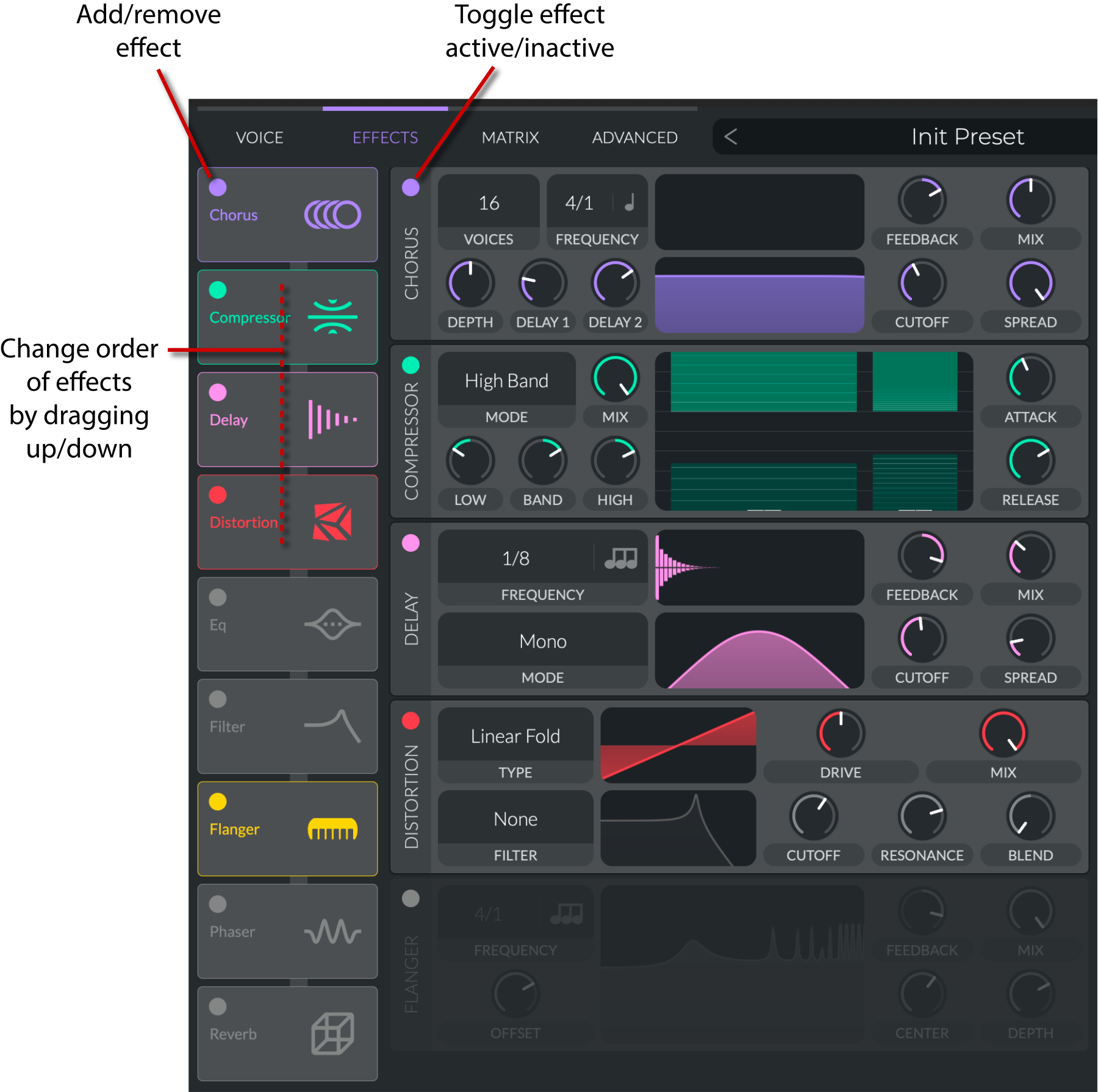
Vital provides a variety of effects that can be used to shape the sound of your patches. The effects can be added to the effects chain in the
Effects
tab:
Chorus
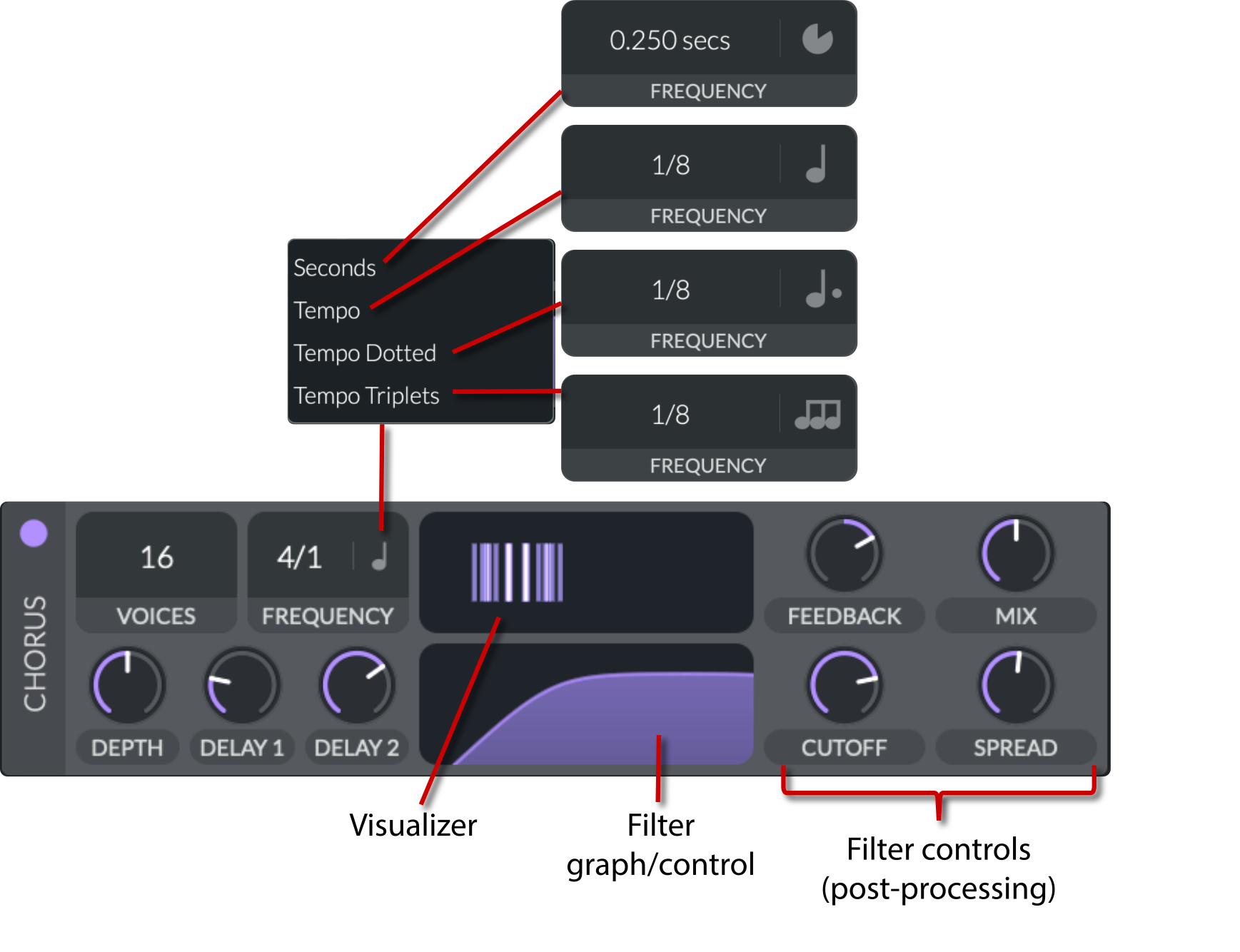
A chorus effect attempts to replicate the phenomenon of multiple voices or instruments playing the same part in unison but with slight variations in timing, pitch, or timbre. This is emulated by duplicating the incoming signal, applying pitch and time modulation (delay) to the copies, and then mixing them with the original signal. The result is a thicker, more spacious tone, reminiscent of several performers sounding together rather than just one.
Voices
(
4 to 16
): Determines the number of delay line pairs (chorus voices) active. More voices enrich the sound by adding several modulated copies.
Frequency
: The modulation frequency which can be tempo-synced using a control that toggles between free-running frequency and beat-synchronized mode, ensuring the chorus movement aligns with the musical tempo.
Seconds
(
0.125 Hz to 64.0 Hz
): Free-running frequency that repeats every
x
seconds.
Tempo
(
Freeze, 32/1 to 1/16
): Sets the speed in musical subdivisions of the host's BPM. Choosing "Freeze" stops the modulation.
Tempo Dotted
(
Freeze, 32/1 to 1/16
): Sets the speed in dotted musical subdivisions of the host's BPM.
Tempo Triplets
(
Freeze, 32/1 to 1/16
): Sets the speed in triplet musical subdivisions of the host's BPM.
Depth
(
0 to 100%
): Controls the modulation depth. It modulates the delay times using a sinusoid, determining how pronounced the time variation is and, therefore, the lushness of the effect.
Delay 1 and Delay 2
(
0.976 ms to 19.99 ms
): These parameters specify the base delay times. They are interpolated to set the delay for each voice. The average of these two delays provides a central value, while interpolation allows for subtle differences, contributing to the stereo width and phase complexity.
Visualizer
: Gives a visual representation of the
Voices
,
Frequency
,
Depth
, and
Delay
parameters.
Feedback
(
-95% to 95%
): Feeds the delayed signal back into the delay lines, enhancing the effect's intensity.
Positive Feedback
:
The delayed signal is fed back as-is (or with only gain adjustment), reinforcing the effect. This tends to enhance the doubling and thickening by constructively adding delayed copies, which can make the effect sound richer but may also risk buildup or resonances if too high.
Negative Feedback
:
The delayed signal is inverted before being fed back. This tends to reduce buildup and can smooth out the effect, sometimes resulting in a more subtle modulation. Negative feedback can help control excess coloration or prevent self-oscillation.
Mix
(
0 to 100%
): The wet/dry mix controls the balance between the original (dry) and the delayed (wet) signals.
Filter (graph/control)
: A graphical representation of the filter applied to the delay signals. It can take the shape of an all-pass, low-pass, high-pass, or band-pass filter by adjusting the
Cutoff
and
Spread
. Drag inside the graph to change the parameters.
Cutoff
(
8 to 136
): Sets the cutoff frequency for the filter applied to the delay signals, shaping the tonal character.
Spread
(
0 to 1
): Adjusts the filter's frequency spread along the delay lines, which can tilt the filter's response to create a broader or tighter effect across the voices.
Compressor
A compressor is used to reduce the dynamic range of a signal. It makes loud parts quieter and/or quiet parts louder, depending on the settings.
Modes
There are
four different modes
you can use:
Multiband
: Splits the signal with filters into low, mid, and high frequencies. Each band is processed independently with its own threshold and ratio settings.
Low Band
: Combines the mid and high bands into a single band and separately processes the low frequencies.
High Band
: Combines the low and mid bands into a single band and separately processes the high frequencies.
Single Band
: Processes the entire frequency range without splitting.
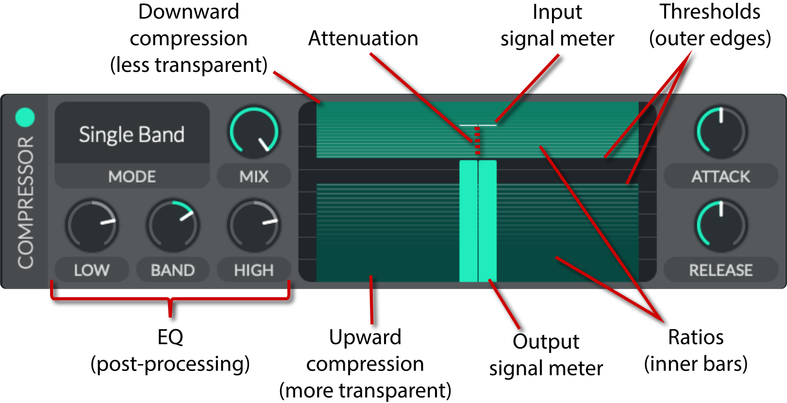
Threshold
Threshold is the dB level at which the compressor starts working. All compressor bands have the same threshold range: -79 dB to -1 dB.
Vital's compressor has both
upward
and
downward
compression capabilities:
Upward compression
: Boosts the signal below the lower threshold. Signals above the threshold remain unaffected.
Downward compression
: Reduces the signal above the upper threshold. Signals below the threshold remain unaffected.
To adjust the threshold, click and drag the outer edge of the compressor band. If you hold
Shift
while dragging, all bands for both compressors will move together.
Ratio
The ratio determines how strongly the compressor reduces or increases the signal level above/below the threshold.
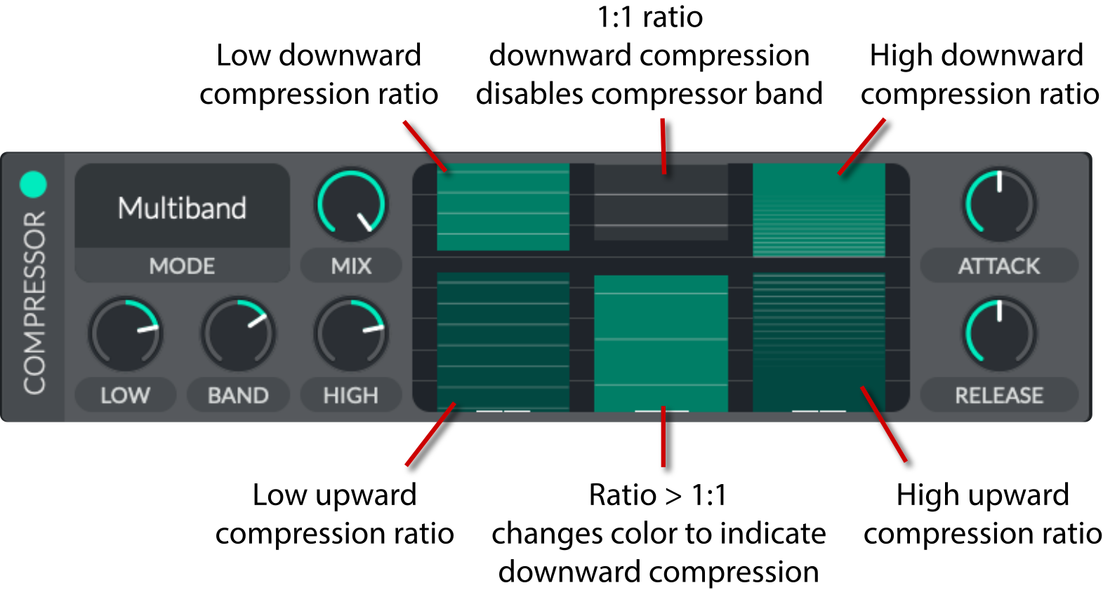
In Vital, the ratio values are not explicitly shown. You can see the approximate value by looking at the number of lines in the compressor. The more lines, the higher the ratio. These are adjustable by clicking and dragging inside the compressor band.
With downward compression, once you get to a ratio of 1:1, the green color will disappear, indicating no compression is applied. This does not happen with upward compression. When going above 1:1 with upward compression, the color will change to that of the downward compressor, indicating downward compression.
The ratios mean different things for upward and downward compression:
In
downward compression
, a 2:1 ratio means for every 2 dB
above
the threshold, it is allowed to rise by only 1 dB.
In
upward compression
, the ratio is inverted, so a 2:1 ratio means for every 2 dB
below
the threshold, the output is boosted by 1 dB.
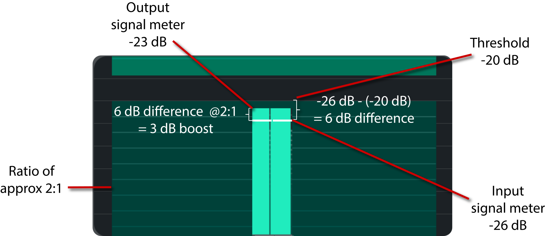
For example, let's consider a scenario with the following settings for
upward compression
:
Threshold
: -20 dB
Ratio
: 2:1
Signal
: -26 dB (6 dB below the threshold)
The
upward compression output
will be -23 dB. Instead of boosting all 6 dB, the signal will be lifted so that it's effectively only 3 dB under the threshold. That means the compressor applies +3 dB of gain to bring the signal up from -26 dB to -23 dB.
Upward compression example
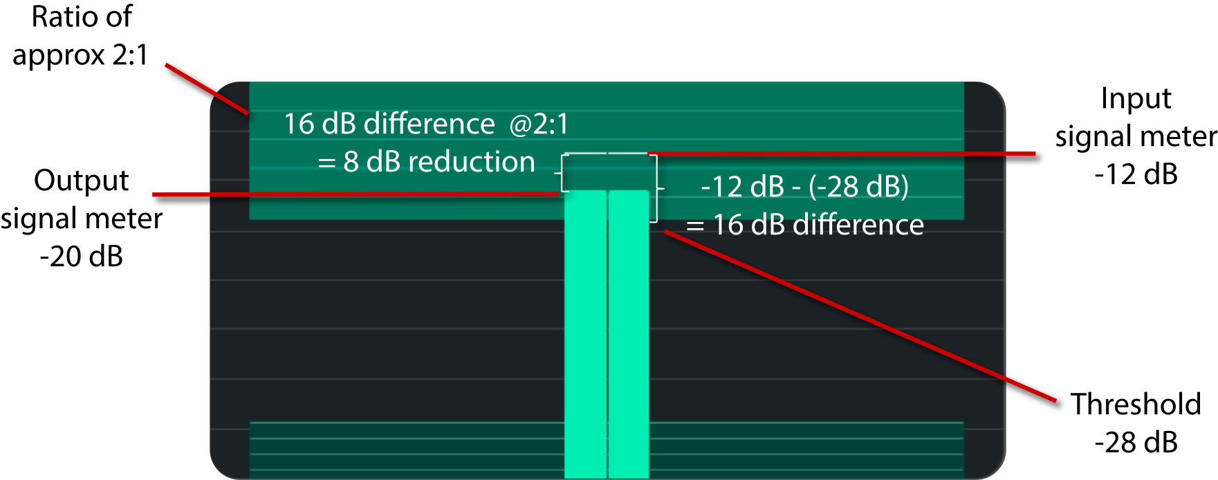
Let's consider a scenario with the following settings for
downward compression
:
Threshold
: -28 dB
Ratio
: 2:1
Signal
: -12 dB (16 dB above the threshold)
The
downward compression output
will be -20 dB. For every 2 dB above the threshold, the output is allowed to rise by only 1 dB. So, the signal will be reduced by 8 dB to bring it down from -12 dB to -20 dB.
Downward compression example
note
Knowing the exact values is not very useful, but understanding the concept is. The visual representations of the ratio, threshold, and input/output levels are a helpful guide.
Attack
The
attack parameter
(
0 to 100%
) controls how quickly the compressor applies its gain change after the signal crosses the threshold. However, its effect manifests a bit differently depending on whether you're compressing downwards (reducing level) or upwards (boosting level).
Downward compression
: The compressor starts working when the input
exceeds
the threshold.
A
fast attack
causes the compressor to reduce the gain as soon as the signal goes above the threshold. This is useful for taming sharp transients (like a snare hit or a vocal plosive) and can result in a "pumping" effect if the attack time is aggressive.
With a
slow attack
, the compressor allows some of the initial transient to pass through uncompressed before reducing the gain. This can preserve the natural impact of the sound, though it might let peaks through that you intended to control.
Upward compression
: The compressor starts working when the input
falls below
the threshold, applying gain to boost the quieter parts.
A
fast attack
promptly lifts quieter parts, making them audible without delay. If too abrupt, it can sound unnatural.
With a
slow attack
, the boost is applied more gradually, leading to a smoother, more natural increase in volume. However, it may not catch very short, quiet events.
Release
The
release
(
0 to 100%
) controls how quickly the compressor stops applying its gain change once the signal moves back toward or beyond the threshold. Just like with attack parameter, the release parameter plays a crucial role in shaping the sound—but its effect differs slightly depending on whether you're dealing with downward or upward compression.
Downward compression
: The compressor reduces the gain when the signal
exceeds
the threshold. Once the signal falls back below the threshold, the compressor needs to "release" its gain reduction and return to normal (unity gain).
Fast Release
:
The gain reduction is removed quickly after the signal falls below the threshold. This rapid recovery can be useful for material with quickly changing dynamics. However, if too abrupt, it can lead to audible artifacts such as "pumping" or a choppy transition, where the level jumps suddenly back up.
Slow Release
:
The compressor takes more time to gradually restore the gain. This results in a smoother, more natural-sounding return to the uncompressed level. The trade-off is that if the release is too slow, the compressor might hold onto the gain reduction longer than desired, potentially dulling the natural dynamics of the sound.
Upward compression
: The compressor boosts the gain when the signal
falls below
the threshold. When the signal rises above the threshold, the extra gain applied needs to be removed, and that's where the release parameter comes into play.
Fast Release
:
The additional gain boost is quickly removed as soon as the signal rises above the threshold. This can be beneficial for ensuring that the boost doesn't linger on louder passages. However, if the release is too fast, the transition back to the unboosted level may sound abrupt, leading to a jarring drop in level.
Slow Release
:
The gain boost is gradually reduced when the signal exceeds the threshold. This gentle recovery can maintain a more natural and seamless dynamic curve. On the downside, if the release is too slow, the compressor might continue to apply extra gain longer than necessary, which can lead to an unnatural-sounding swell or a lack of clarity in the transitions between quiet and louder passages.
EQ
Low/Band/High
: EQ for the post-compression signal.
Delay
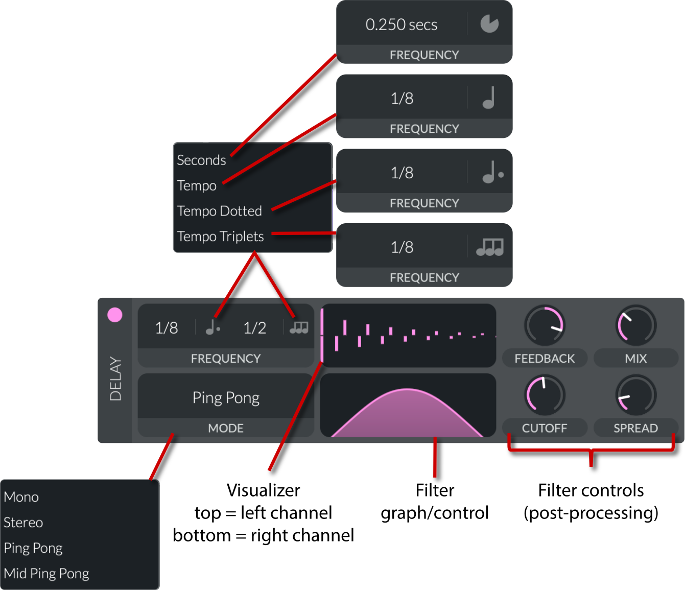
Vital's delay effect applies time-based echoes with modulation and filtering. You can achieve effects that range from clean, rhythmic echoes to more saturated, filtered repetitions with rich spatial characteristics.
Frequency (sync)
:
Controls the delay time by setting the base frequency of the delay line. It can operate as a free-running frequency (directly controlling delay time) or be tempo-synced (using a beats-per-minute reference) so that the echoes align rhythmically with the music.
Seconds
(
0.001 Hz to 4.0 Hz
): Free-running frequency that repeats every
x
seconds.
Tempo
(
4/1 to 1/64
): Sets the speed in musical subdivisions of the host's BPM.
Tempo Dotted
(
4/1 to 1/64
): Sets the speed in dotted musical subdivisions of the host's BPM.
Tempo Triplets
(
4/1 to 1/64
): Sets the speed in triplet musical subdivisions of the host's BPM.
Mode
:
Mono
: A simple delay where a single delay line is applied equally to both channels.
Stereo
: Uses separate delay times for left and right channels to create a wider image.
Ping Pong
: Alternates the delayed signal between the left and right channels, creating a bouncing echo effect.
Mid Ping Pong
: Similar to ping pong but uses a mid-image source to blend some channels before alternating, providing a slightly different spatial feel.
Feedback
(
-100% to 100%
): Determines the proportion of the delayed (echoed) signal that is fed back into the delay line.
Positive Feedback
:
The delayed signal is fed back in-phase (or without phase inversion). This reinforces the echoes, potentially increasing their amplitude and creating a denser, sometimes more resonant or even self-oscillating effect if pushed too high.
Negative Feedback
:
The delayed signal is inverted before being fed back. This tends to cancel or attenuate some aspects of the repeated echoes, producing a cleaner or more controlled decay. It often results in less buildup and can reduce the risk of runaway oscillations.
Mix
(
0 to 100%
):
Sets the balance between the dry (unprocessed) signal and the wet (delayed) signal. It controls how prominently the delay effect is heard in the final output.
Filter (graph/control)
: A graphical representation of the filter applied to the delay signals. It can take the shape of an all-pass, low-pass, high-pass, or band-pass filter by adjusting the
Cutoff
and
Spread
. Drag inside the graph to change the parameters.
Cutoff
(
8 to 136
):
Applies internal filtering to the delayed signal using one-pole filters. The cutoff frequency controls which frequencies are attenuated, typically damping very low or high frequencies to create a more polished, natural echo.
Spread
(
0 to 1
):
Adjusts the filter's frequency spread around the cutoff frequency. This parameter modifies how broadly the filter affects the delayed signal's spectrum, allowing for subtle tonal shaping of the echoes.
Distortion
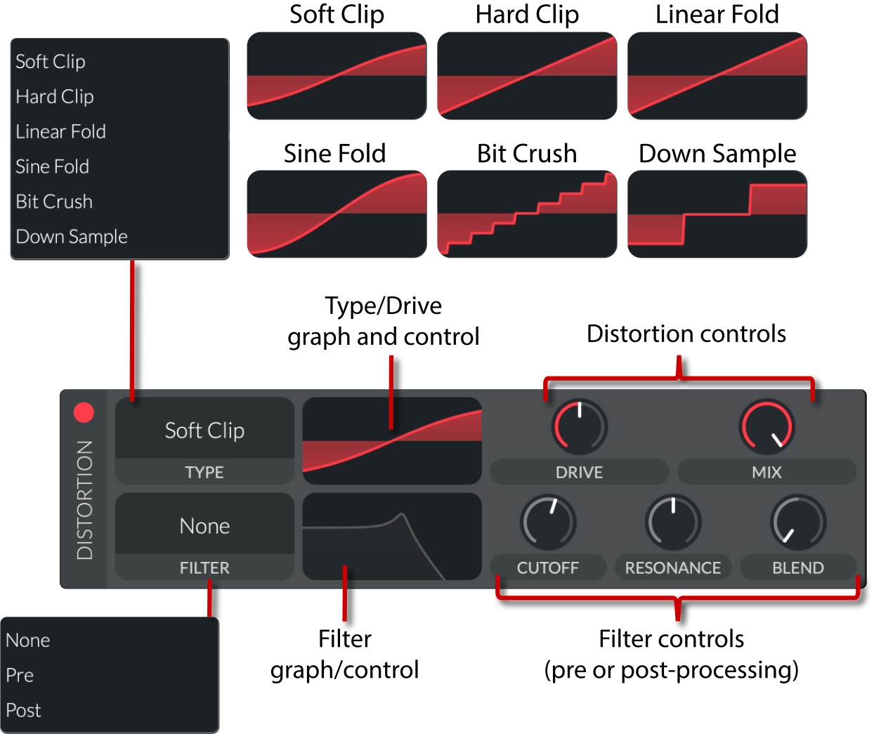
Vital's distortion effect shapes the incoming audio signal using several selectable algorithms and an optional filtering stage. The overall signal is processed based on a drive value before blending with the original signal using a mix control. An extra filter stage can be applied either before or after distortion to further sculpt the tone.
The interface is divided into controls for the distortion and controls for the filter.
Distortion controls
:
Type
: Determines the algorithm used:
Soft clip
: Uses a hyperbolic tangent (tanh) function to softly compress the peaks.
Hard clip
: Clamps the signal abruptly after amplification, leading to a more aggressive effect.
Linear fold
: Scales and offsets the signal, then repeatedly "folds" it back into the [-1, 1] range.
Sine fold
: Maps the signal using a sine function for a smoother, more musical waveshaping.
Bit crush
: Quantizes the sample values (rounding to a fixed step size) to simulate low-resolution digital sound.
Down sample
: Reduces the effective sample rate, introducing aliasing and a gritty digital effect.
Type/Drive graph and control
: A visual representation of the distortion type and drive level. Drag inside the graph to adjust the drive.
Drive
(
-30 dB to 30 dB
): Adjusts the gain applied to the input signal before distortion, determining how hard the effect is driven. A higher drive increases the intensity of distortion.
Mix
(
0 to 1
): Blends the dry (original) signal with the processed (distorted) signal. A mix control allows you to dial in subtle warmth or extreme distortion.
Filter controls
: The filter can be adjusted to act as a low-pass, high-pass, band-pass, or peak filter. It can be applied before or after the distortion stage, shaping the spectral content of the signal.
Filter (mode)
:
None
: No filtering is applied.
Pre
: The filter is applied before the distortion stage, altering the input waveform.
Post
: The filter is applied after distortion, smoothing or accentuating the distorted signal.
Filter graph and control
: A graphical representation of the filter applied to the signal. Drag inside the graph to adjust the filter parameters.
Cutoff
(
8 to 136 semitones
): The cutoff frequency sets the point where filtering starts to attenuate frequencies. This shapes the spectral content of the signal.
Resonance
(
0 to 100%
): Works with the cutoff by emphasizing frequencies around the cutoff point, adding a peak to the filter's response that can accentuate certain harmonics.
Blend
(
0 to 2
): Controls the mix between different filter outputs (for example, mixing between the low-pass and high-pass—or, more generally, filtered and unfiltered—contents) so that you can fine-tune the tonal coloration imposed by the filter on the distorted sound. A higher blend value emphasizes the filter's contribution, altering the timbre more, while a lower blend preserves more of the raw distortion character.
EQ
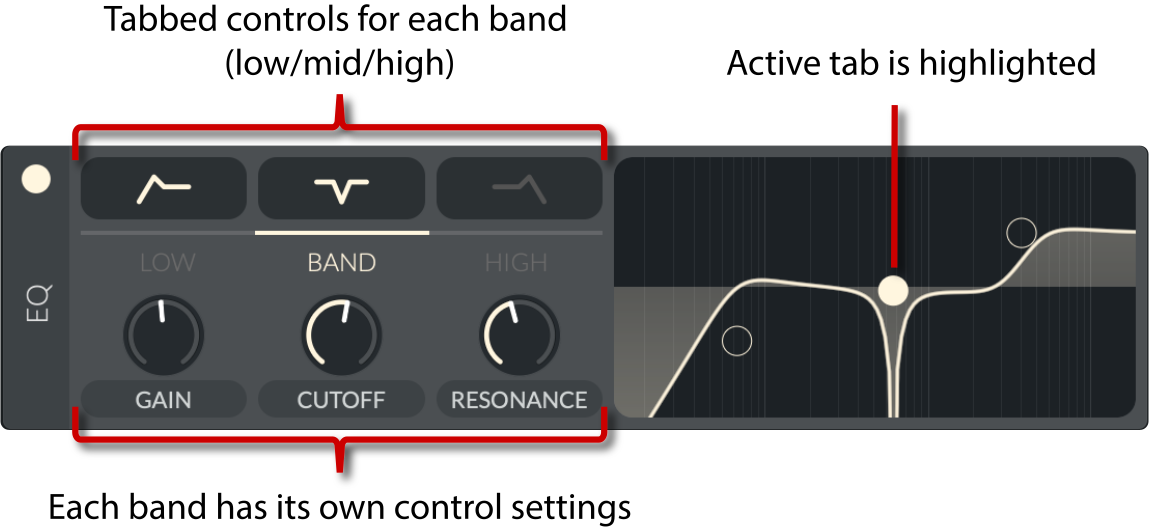
Vital's equalizer effect is implemented as a three-band processor that splits the audio into low, mid ("band"), and high frequency regions. These regions can be independently adjusted via the graph as well as the knobs. Each band has separate settings for gain, cutoff, and resonance.
Low/Band/High
:
These refer to the three separate frequency sections of the EQ. Each band can be set to different filter modes (for example, low band may use a shelving or high-pass filter, mid band can use a shelving or notch filter, and high band may use a shelving or low-pass filter) in order to target the desired part of the frequency spectrum.
Gain
(
-15 dB to 15 dB
):
The gain parameter for each band controls the amount of boost or cut applied to signals in that frequency region. Adjusting gain alters the amplitude of the band, shaping the overall tonal balance of the audio.
Cutoff
(
8 to 136 semitones
):
The cutoff value determines the transition frequency at which the filter begins to operate. For a shelf filter, it sets the point where boosting or attenuating starts; for a notch filter, it marks the center of the frequency dip. This frequency can be modulated for dynamic EQ adjustments.
Resonance
(
0 to 100%
):
Also known as the Q factor, resonance adjusts the emphasis at the cutoff frequency. A higher resonance results in a more pronounced peak (or dip), sharpening the filter's response around the cutoff and potentially adding character or coloration to the sound.
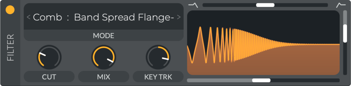
Filter
The filter used as an effect is exactly the same as the filters in the Voice tab, except there are no routing options. Refer to the
Filters
section for more information.
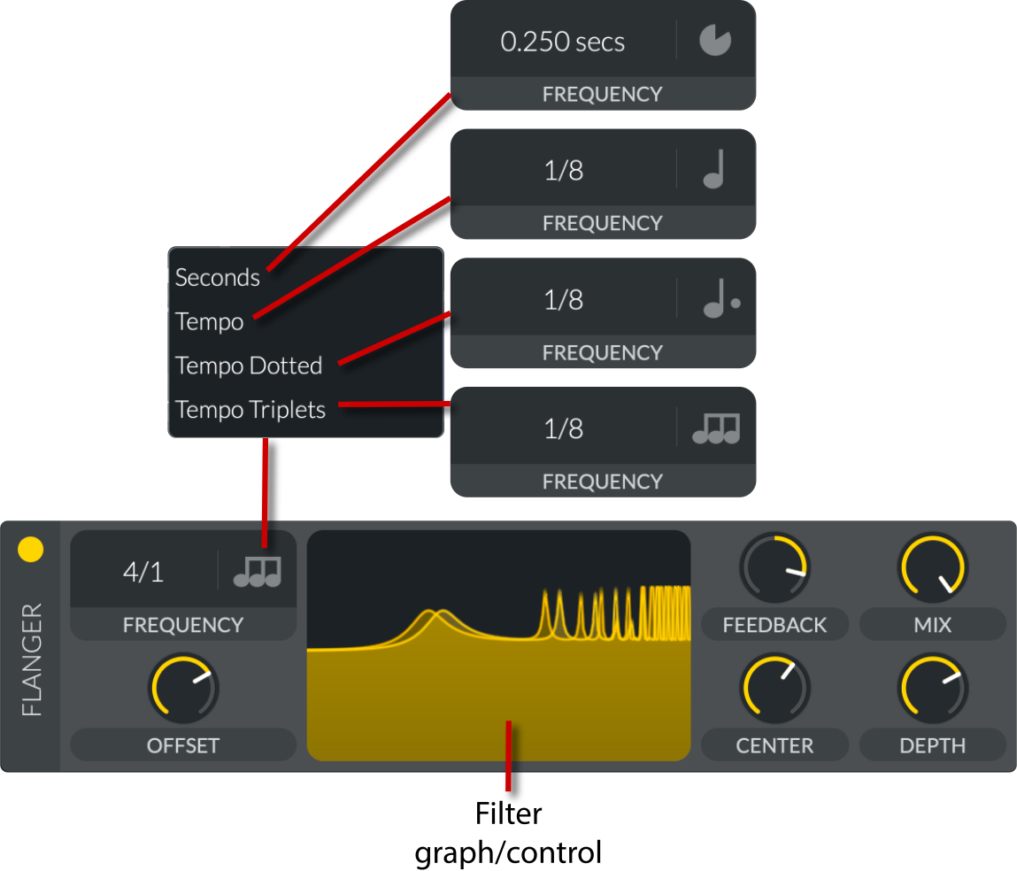
Flanger
Vital's flanger effect is implemented using a modulated delay line that varies the delay over time, creating the classic sweeping, "whooshing" sound. The effect can range from subtle shimmer to bold, dramatic sweeps.
Frequency (sync)
:
Controls the speed of the LFO that modulates the delay time, which can be tempo-synced using a control that toggles between free-running frequency and beat-synchronized mode, ensuring the flanger's sweep moves in time with the musical tempo.
Seconds
(
0.250 Hz to 32 Hz
): Free-running frequency that repeats every
x
seconds.
Tempo
(
Freeze, 32/1 to 1/16
): Sets the speed in musical subdivisions of the host's BPM.
Tempo Dotted
(
Freeze, 32/1 to 1/16
): Sets the speed in dotted musical subdivisions of the host's BPM.
Tempo Triplets
(
Freeze, 32/1 to 1/16
): Sets the speed in triplet musical subdivisions of the host's BPM.
Offset
(
0 to 360 degrees
):
Adjusts the phase difference between left and right modulation (the "phase offset"). This creates a stereo effect by causing the delay time on one channel to lead or lag the other, enhancing the spatial movement.
Feedback
(
-100% to 100%
):
Determines how much of the processed (flanged) signal is fed back into the delay line. Increasing feedback strengthens the resonance and can create a more pronounced, swirling effect.
Positive Feedback:
The delayed signal is fed back without phase inversion. This reinforces the comb-filtering effect, making the notches and peaks more pronounced and adding resonance to the sweep.
Negative Feedback:
The delayed signal is inverted before being fed back. This tends to smooth out the response and reduce excessive resonance, leading to a subtler, sometimes cleaner modulation character.
Mix
(
0 to 100%
):
Sets the balance between the dry (unprocessed) signal and the wet (flanged) signal. A higher mix value makes the flanger effect more prominent in the output.
Center
(
8 to 136 semitones
):
Establishes the base delay time around which the LFO modulates. This "center" value is typically derived from a MIDI note conversion, setting the core delay duration that the modulation oscillates around.
Depth
(
0 to 100%
):
Controls the amount by which the delay time deviates from the center value. Greater depth results in more dramatic variations in delay time, yielding a wider, more intense flanging sweep.
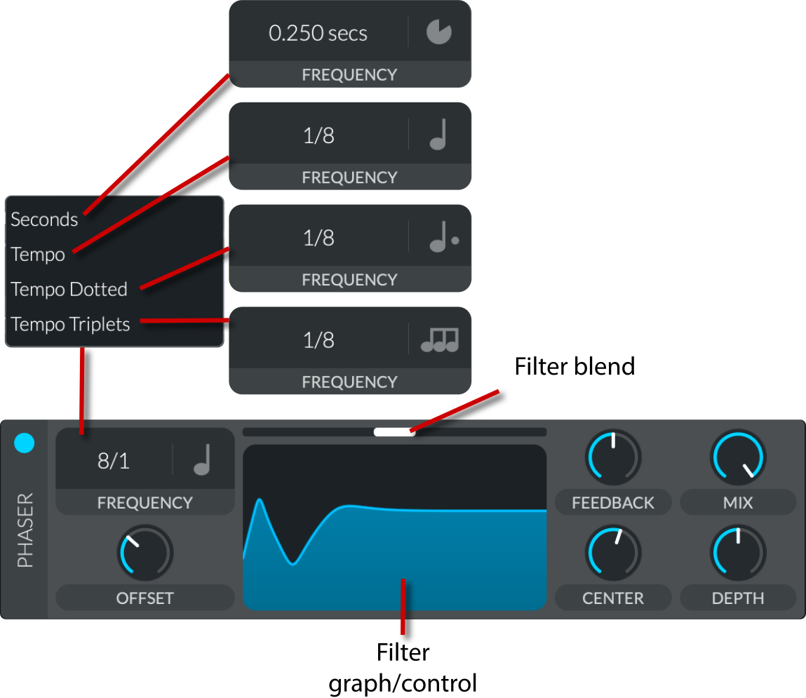
Phaser
Vital's phaser effect modulates a series of all-pass filter stages using an LFO to create sweeping notches and peaks in the frequency response. It allows fine control over the dynamic and spatial characteristics of the phaser, from subtle shimmer to dramatic, sweeping effects.
Frequency (sync)
:
Sets the LFO rate that modulates the filter cutoff, which can be tempo-synced using a control that toggles between free-running frequency and beat-synchronized mode, ensuring the sweeping motion plays rhythmically with the music.
Seconds
(
0.250 Hz to 32 Hz
): Free-running frequency that repeats every
x
seconds.
Tempo
(
Freeze, 32/1 to 1/16
): Sets the speed in musical subdivisions of the host's BPM.
Tempo Dotted
(
Freeze, 32/1 to 1/16
): Sets the speed in dotted musical subdivisions of the host's BPM.
Tempo Triplets
(
Freeze, 32/1 to 1/16
): Sets the speed in triplet musical subdivisions of the host's BPM.
Offset
(
0 to 360 degrees
):
Adjusts the phase offset of the modulation. This can introduce a stereo spread by shifting the LFO's phase between channels, giving the effect more spatial width.
Blend
(
0 to 2
): Morphs between fewer and more notches in the frequency spectrum. This is the same as it is for the
phaser filter
.
Feedback
(
0 to 100%
):
Controls how much of the processed signal is fed back into the filter. Higher feedback increases resonance, deepening the notches and peaks in the effect's frequency response.
Mix
(
0 to 100%
):
Balances the dry (original) signal with the wet (phased) signal. A higher mix value makes the phasing effect more pronounced.
Center
(
8 to 136 semitones
):
Determines the base cutoff frequency (typically specified as a MIDI note value) around which the LFO modulates. This sets the "central" position of the notches and is key to shaping the overall tonal character.
Depth
(
0 to 48 semitones
):
Modulates the extent of the cutoff variation. Greater depth results in a wider sweep of the filter's cutoff frequency, intensifying the phaser's characteristic movement.
Reverb
Vital's reverb effect creates a spacious, immersive sound by driving the input signal through a dense network of all-pass filters and feedback delay lines. This simulates the complex reflections found in physical spaces. The reverb module also offers multiple filtering and modulation options for fine-tuning the character of the reverb tail.
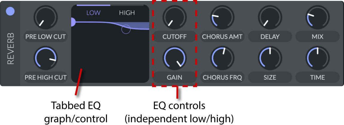
Pre low cut
(
0 to 128 semitones
):
A filter applied to the input before it enters the reverb network that attenuates very low frequencies. This helps remove unwanted low-end rumble and keeps the reverb clearer.
Pre high cut
(
0 to 128 semitones
):
A complementary filter on the input that attenuates excessive high frequencies, ensuring the reverb does not become too bright or harsh.
EQ (tabbed low/high graph)
:
A visual and interactive control that lets you choose which of the feedback EQ bands (low shelf or high shelf) you want to adjust. Toggling between these on the graph updates which frequency band's
Cutoff
and
Gain
are being controlled.
Cutoff
(
0 to 128 semitones
):
In the feedback EQ, the cutoff defines the frequency at which the shelving filter begins to affect the feedback signal. It shapes the tonal balance of the reverb tail by emphasizing or de-emphasizing a portion of the frequency spectrum.
Gain
(
-6 dB to 0 dB
):
Adjusts the amplitude of the filtered feedback path. In combination with the cutoff controls, it determines how strongly a particular EQ band (low or high) is emphasized within the reverb tail.
Chorus amt
(
0 to 100%
):
Determines how much chorus modulation is applied to the reverb tail. Adding chorus smears the reflections slightly, creating a thicker, more diffused sound.
Chorus Frq
(
0 to 8 Hz
):
Controls the speed (frequency) of the chorus modulation. Faster modulation results in a more rapidly fluctuating character, while slower modulation creates a gentler, more undulating movement.
Delay
(
0 to 0.3 s
):
Sets the pre-delay time before the reverb kicks in. A longer delay creates more separation between the dry sound and its reverberated reflections, simulating a larger physical space.
Size
(
0 to 100%
):
Simulates the dimensions of the reverb space. A larger size parameter typically results in longer delays and a more expansive tail, making the effect sound as if it's in a bigger room or hall.
Mix
(
0 to 100%
):
The dry/wet mix balances the level of the unaffected (dry) signal versus the processed (wet) reverb. Adjust it to control how dominant the reverb is in the final output.
Time
(
0.015 s to 64 s
):
Determines the decay time of the reverb tail—that is, how long it takes for the reverb to fade to an almost inaudible level. This parameter is central to defining the overall ambience and character of the reverberation.
V43 | Effects tab
Effects.html | documentation and visible configuration; not a new native test
Effects
Retained observation
FX are activated independently and reordered by dragging. The example chain contains chorus, compressor, delay, distortion and flanger, with other families available. Reordering changes which signal drives later stages. Preserve order, enable state and parameters, not an unordered set of effects or a wetness total.
Source SHA-256: 519e93c81ec0bee385339a61add29e0ff8625e51b394c58bb2beb03513cb7664 Image SHA-256: f58ecaf68c73b016a24f64aec812463cf6a9e474efc84f6d591472b91d344cfa Original URL: https://davidmvogel.com/img/vital-images/effects-tab.svg
V44 | Chorus effect
Effects.html | documentation and visible configuration; not a new native test
Chorus
Retained observation
Chorus contains voices, rate domain, depth, two delay groups, feedback and mix, plus filtered output controlled by cutoff/spread. It is a time-varying delayed path, distinct from oscillator unison. Source pitch/phase and chorus delay motion can be allocated separately instead of encoding both in extracted stereo tables.
Source SHA-256: 519e93c81ec0bee385339a61add29e0ff8625e51b394c58bb2beb03513cb7664 Image SHA-256: e4c818d41fa8a458d3fd9a4cd534989042cd343643d4d7f57abe6a142196226c Original URL: https://davidmvogel.com/img/vital-images/chorus.svg
V45 | Compressor effect
Effects.html | documentation and visible configuration; not a new native test
Compressor
Retained observation
The compressor's outer graph edges are thresholds and inner bars are ratios; the central bars show input/output and attenuation. Upper/lower regions control different level behavior; attack/release and band gains are separate. The figure's "more transparent" description of upward compression is contextual, not a rule that it is always less audible or improves a match.
Source SHA-256: 519e93c81ec0bee385339a61add29e0ff8625e51b394c58bb2beb03513cb7664 Image SHA-256: f44d3b4b58d1dbd876f9691ee1b12e0547594bfe2eea7160d4d6ebb276da65c1 Original URL: https://davidmvogel.com/img/vital-images/compressor.svg
V46 | Compressor effect with bands
Effects.html | documentation and visible configuration; not a new native test
Modes
Retained observation
Multiband, Low Band, High Band and Single Band visibly change the active band layout. Select the detector/processing organization before tuning gains and thresholds. A static EQ adjustment and band-dependent dynamic shaping can give different articulation even when an averaged spectrum looks similar.
Source SHA-256: 519e93c81ec0bee385339a61add29e0ff8625e51b394c58bb2beb03513cb7664 Image SHA-256: 01f19df7a5d0d7bb6dce4b9bb37748bc6adb7a60d6e960d0db68d62d0624790e Original URL: https://davidmvogel.com/img/vital-images/compressor-bands.svg
V47 | Compressor effect with ratios
Effects.html | documentation and visible configuration; not a new native test
Ratio
Retained observation
Ratio graphics distinguish weak/strong upper and lower processing, with a 1:1 upper region displayed as disabled. Do not interpret that label as bypassing every operation in the band: lower processing and gain have separate controls. The lower-region color change is a useful UI cue; exact expansion semantics stay linked to the existing source-backed compressor notes.
Source SHA-256: 519e93c81ec0bee385339a61add29e0ff8625e51b394c58bb2beb03513cb7664 Image SHA-256: 71119fb79f018ff2fe4ebbf8a8d53649517c2829108fc310b124b1e4d273e65d Original URL: https://davidmvogel.com/img/vital-images/compressor-ratios.svg
V48 | Upward compression example
Effects.html | documentation and visible configuration; not a new native test
Ratio
Retained observation
The illustrative upward-compression meter maps input -26 dB toward threshold -20 dB at approximately 2:1, giving output -23 dB. It explains below-threshold gain rather than uniform makeup gain. Keep the displayed example arithmetic, not a claim that this was measured from our plugin or reference audio.
Source SHA-256: 519e93c81ec0bee385339a61add29e0ff8625e51b394c58bb2beb03513cb7664 Image SHA-256: ebc61f6b1a8697bde5b61dcd0d32736d450d91459541c4e6f8f6e447cb16702e Original URL: https://davidmvogel.com/img/vital-images/upward-compression-example.svg
V49 | Downward compression example
Effects.html | documentation and visible configuration; not a new native test
Ratio
Retained observation
The downward example maps input -12 dB above threshold -28 dB at approximately 2:1 to output -20 dB. Together with V48 this distinguishes upper and lower threshold action. Real transients also depend on detector history and timing; these static examples do not specify the entire dynamic response.
Source SHA-256: 519e93c81ec0bee385339a61add29e0ff8625e51b394c58bb2beb03513cb7664 Image SHA-256: 52e86139f314f9ba76ad8165a4440539f06f6e3ce467075474212183bb6850ed Original URL: https://davidmvogel.com/img/vital-images/downward-compression-example.svg
V50 | Delay effect
Effects.html | documentation and visible configuration; not a new native test
Delay
Retained observation
Delay offers Mono, Stereo, Ping Pong and Mid Ping Pong, two time controls and seconds/tempo subdivisions. The visualization explicitly separates L/R repeat positions. Cutoff/spread shape the delayed path. Preserve timing and routing so echo structure is not mistaken for extra notes, release or oscillator width.
Source SHA-256: 519e93c81ec0bee385339a61add29e0ff8625e51b394c58bb2beb03513cb7664 Image SHA-256: 6ea6ffc405f041752e1851138f00c3155cc604f22785c9f2e5475e11e85b5395 Original URL: https://davidmvogel.com/img/vital-images/delay.svg
V51 | Distortion effect
Effects.html | documentation and visible configuration; not a new native test
Distortion
Retained observation
Six distinct distortion types have separate plotted responses: Soft/Hard Clip, Linear/Sine Fold, Bit Crush and Down Sample. The internal filter can be None, Pre or Post with cutoff/resonance/blend. Pre filtering changes what excites the nonlinearity; post filtering shapes its output. Drive and mix must be retained with upstream level, not treated as a final loudness adjustment.
Source SHA-256: 519e93c81ec0bee385339a61add29e0ff8625e51b394c58bb2beb03513cb7664 Image SHA-256: fe4ed052c1a3ea364a34ba9d96145adf43202f0cb93adcaa073a731c0a09eee5 Original URL: https://davidmvogel.com/img/vital-images/distortion.svg
V52 | EQ effect
Effects.html | documentation and visible configuration; not a new native test
EQ
Retained observation
EQ shows three independently configured tabs and multiple graph handles. The example combines low cut, mid notch and high shelf. Each band's gain/cutoff/ resonance and mode survive tab changes; the visible selected band is not the whole EQ. This is a compact way to keep global spectral shaping editable.
Source SHA-256: 519e93c81ec0bee385339a61add29e0ff8625e51b394c58bb2beb03513cb7664 Image SHA-256: 89b13691dd3fe5a1b5c062ba4fafd2d9241f852f3c508ee4f31db64a24917bd9 Original URL: https://davidmvogel.com/img/vital-images/eq.svg
V53 | Filter effect
Effects.html | documentation and visible configuration; not a new native test
Filter
Retained observation
The FX filter example uses Comb: Band Spread Flange-, with Cut, Mix and Keytrack plus graph controls. The effects slot has a wide family vocabulary, not just another low-pass. Its location after the voice sum differs from two separately routed voice filters, especially with overlapping notes or nonlinearity.
Source SHA-256: 519e93c81ec0bee385339a61add29e0ff8625e51b394c58bb2beb03513cb7664 Image SHA-256: 3225f406e4df48f846d344650164ce9fa45bf519a2de50cfcd50aa8c3ae413d1 Original URL: https://davidmvogel.com/img/vital-images/filter.svg
V54 | Flanger effect
Effects.html | documentation and visible configuration; not a new native test
Flanger
Retained observation
Flanger combines rate, offset, center, depth, feedback and mix with a comb-like response graph. Center sets the region around which delay-driven coloration moves, depth sets excursion and offset affects stereo relationship. Preserve these dependencies instead of reducing the operation to "make wider."
Source SHA-256: 519e93c81ec0bee385339a61add29e0ff8625e51b394c58bb2beb03513cb7664 Image SHA-256: d56e7503217e073e6abe3b6ccaa0c2ac808f032c43a13f6e5bb868b25a032608 Original URL: https://davidmvogel.com/img/vital-images/flanger.svg
V55 | Phaser effect
Effects.html | documentation and visible configuration; not a new native test
Phaser
Retained observation
Phaser has a similar timing layout but a distinct response and an additional filter-blend slider. Center/depth and response blend allow moving notches or a more static coloration. Similar controls do not make phaser and flanger interchangeable; retain their mechanism and resulting movement separately.
Source SHA-256: 519e93c81ec0bee385339a61add29e0ff8625e51b394c58bb2beb03513cb7664 Image SHA-256: 61485cfb6e1c398dbba55772c403a06cb8ed6f6d36bbc299d1fff300eba445be Original URL: https://davidmvogel.com/img/vital-images/phaser.svg
V56 | Reverb effect
Effects.html | documentation and visible configuration; not a new native test
Reverb
Retained observation
Reverb separates pre-low/high cuts, independent low/high EQ tabs, chorus amount/rate, delay, size, time and mix. This supports frequency-dependent tail behavior and internal modulation. Use the source-backed feedback-EQ placement when modeling decay; the diagram's generic EQ label alone does not establish an external post-reverb EQ topology.
Source SHA-256: 519e93c81ec0bee385339a61add29e0ff8625e51b394c58bb2beb03513cb7664 Image SHA-256: e8590cb5c21a2a96a561314165ca1b6906f4831f62727ec0c84b83b66866b635 Original URL: https://davidmvogel.com/img/vital-images/reverb.svg