Offline source reader | preserved content, not new verification
Filters | David Vogel
Preserved third-party source, not an ORMAN project instruction. Complete extracted article text is followed by every retained figure and its separately labeled project observation. Original files remain unchanged. For PDFs, use the original page images when extracted glyphs are unclear. Linked external audio/video and external repository trees were not part of the retained snapshot.
Vital Software Synthesizer
Vital User Guide
Filters
On this page
Filters
There are two filters on the Voice tab. Vital provides a wide variety of options including
analog, digital
,
diode
,
formant
,
comb
, and
phaser
filters. The filters can be used in series or parallel and can be modulated by various sources.
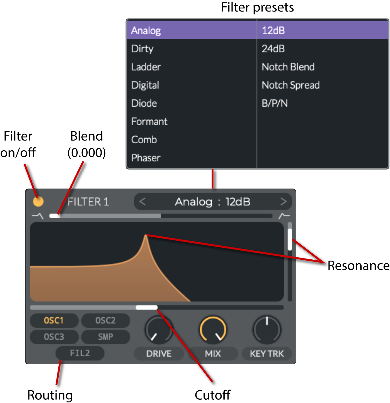
The controls for the filters differ depending on what filter type is selected. You can drag on the filter graphic to change certain parameters like cutoff and resonance.
Analog, Dirty, Ladder, & Digital Filters
These models represent "classic" filter circuits, each with slight variations in character.
They all have the following options:
Power Button
: Turns the filter on or off.
Blend
(
0 to 2
): Blend between the filter types.
This acts differently depending on the filter type:
12dB/24dB
: Morphs between low-pass, band-pass, and high-pass. 12dB means that the filter attenuates the signal at 12dB per octave. 24dB means that the filter attenuates the signal at 24dB per octave.
Notch Blend
: Morphs between low-pass, notch, and high-pass.
Notch Spread
: Morphs between band-pass, double-notch, and notch.
B/P/N (Band/Peak/Notch)
: Morphs between band-pass, peak, and notch.
Preset menu
: Provides a list of presets for the filter.
Resonance
: Adjusts the resonance of the filter. Resonance is the emphasis of the frequencies near the cutoff frequency.
Routing
: Toggles for sources that are sent to the filter.
The options are all of the other modules in the Voice tab: Osc 1/2/3, Sampler, and the other Filter (1 or 2).
Drive
(
0 to 20dB
): Adds saturation to the filter. Saturation is a type of distortion that can add harmonics to the sound.
Mix
(
0 to 100%
): Adjusts the mix between the dry and wet signals.
Key Tracking
(
-100% to 100%
): Adjusts the key tracking of the filter. Key tracking is the adjustment of the filter cutoff frequency based on the pitch of the note being played. At negative values, the filter cutoff frequency decreases as the pitch increases. At positive values, the filter cutoff frequency increases as the pitch increases.
Cutoff
(
-52 to 76 semitones
): Adjusts the cutoff frequency of the filter. The cutoff frequency is the point at which the filter starts to attenuate the signal.
The general filter types are as follows:
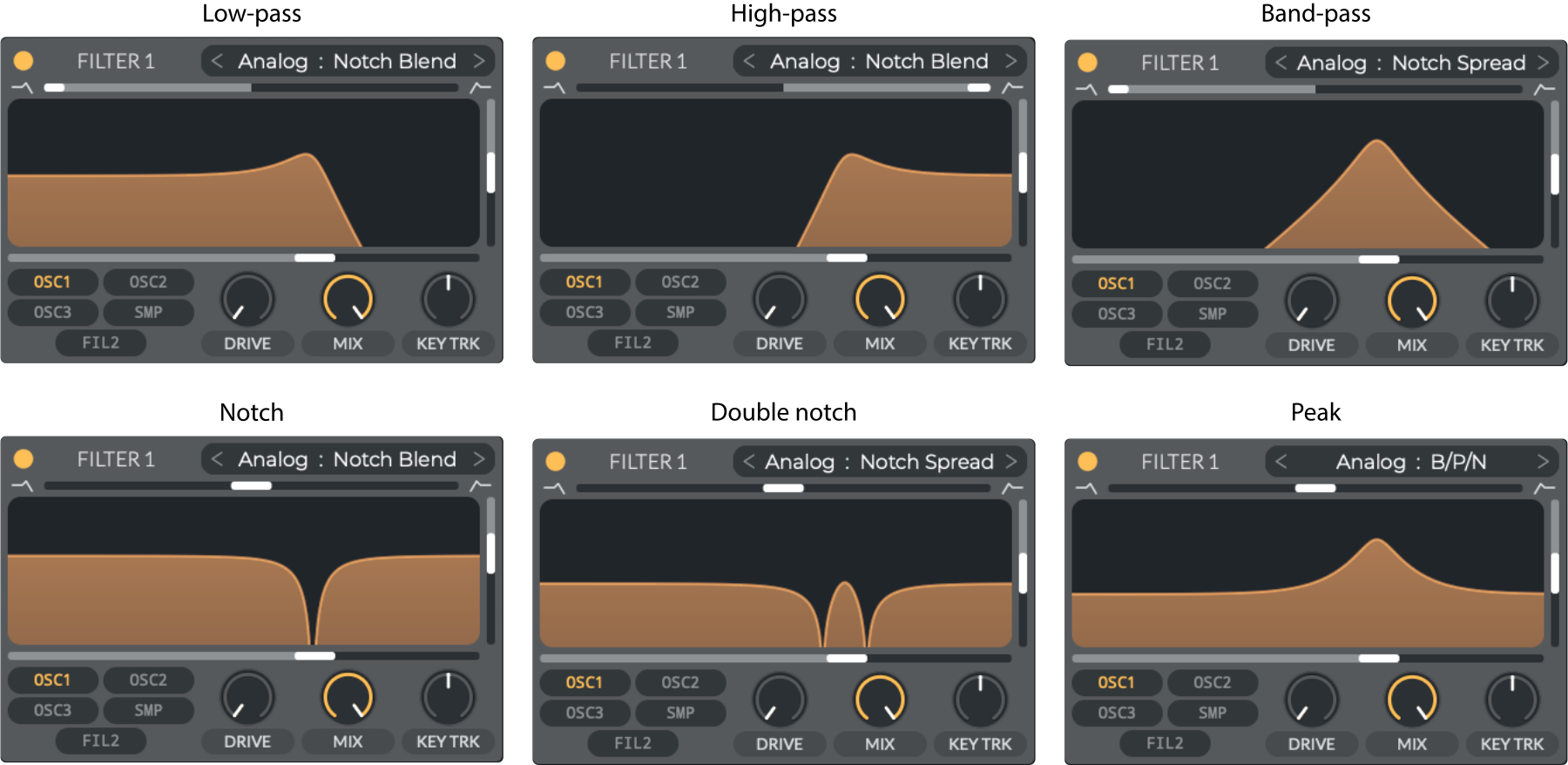
Low-pass
: Allows frequencies below the cutoff frequency to pass through.
High-pass
: Allows frequencies above the cutoff frequency to pass through.
Band-pass
: Allows frequencies between two cutoff frequencies to pass through.
Notch
: Attenuates frequencies between two cutoff frequencies.
Double-notch
: Same as a notch filter but with two notches.
Peak
: Emphasizes frequencies between two cutoff frequencies.
The following are brief descriptions of the filter categories:
Analog
: Emulates classic analog filter circuits.
Ladder
: Emulates classic
transistor ladder filters
which were used in the original Moog synthesizers.
Dirty
: Provides a grittier, non-clean filtering option.
Digital
:
A state-variable filter (SVF)
that can morph among multiple filter responses.
Diode filter
The Diode filter is a
diode ladder filter
that models nonlinear behavior such as soft clipping or saturation. This means that as the signal level increases, the diodes start to conduct more, subtly distorting the signal in an unpredictable way.
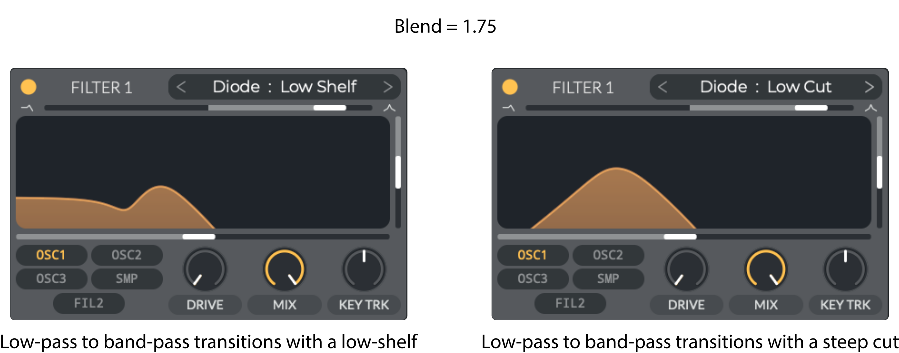
As with the previous filters, the Diode filter has controls for resonance, cutoff, drive, mix, and key tracking. It also has the following options:
Low Shelf
: Morphs from a low-pass to a band-pass filter. When transitioning from low-pass to band-pass, the filter has a shelf at the cutoff frequency.
Low Cut
: Exhibits the same morphing behavior as Low Shelf but with a different curve, resulting in a steep cutoff when transitioning from low-pass to band-pass:
Formant filter
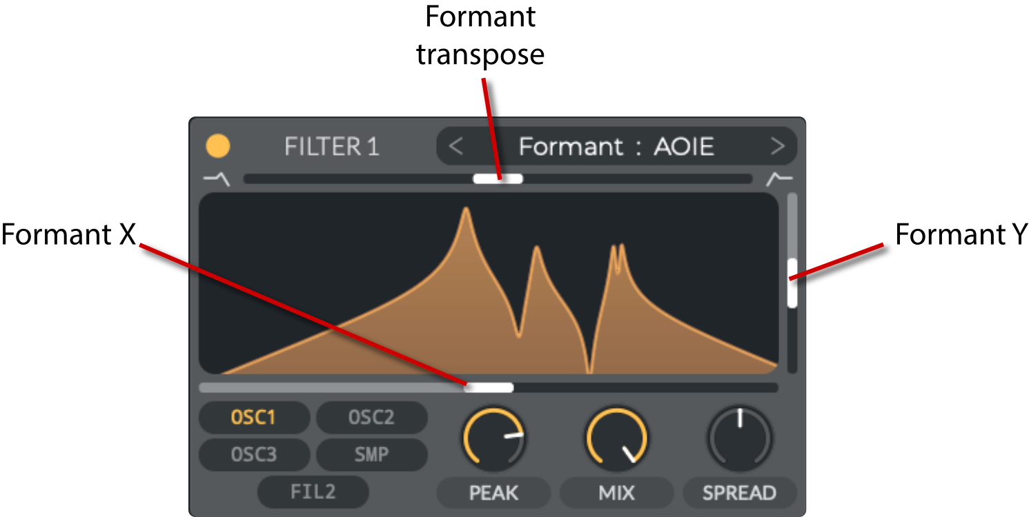
Formant filters are designed to mimic the resonances of vowel sounds from the human voice. This is achieved by using band-pass filters that are tuned to the formant frequencies of vowels.
Some of the controls for this filter are quite different from the previous filters:
Formant transpose
(
-12 to 12 semitones
): Transposes the formant frequencies.
Formant X
(
0 to 1
): Adjusts the formant frequencies along the X-axis.
Formant Y
(
0 to 1
): Adjusts the formant frequencies along the Y-axis.
Peak
(
30% to 100%
): Adjusts the peaks of the formant filter.
Spread
(
-100% to 100%
): Adjusts the spread of the formant filter. Negative values will make the formants further apart, while positive values will make them closer together, converging on a single formant.
AOIE
: The filter's resonant peaks are arranged to emulate the spectral characteristics of these vowel sounds.
AIUO
: Similarly, this represents the vowels A, I, U, and O.
Comb filter
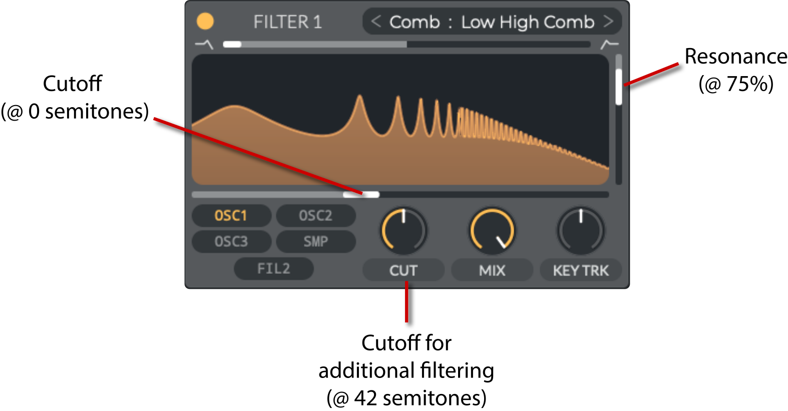
Comb filters are created by feeding a signal back into itself with a delay, which produces a series of notches in the frequency spectrum that resemble a comb when graphed:
The controls for the comb filter are similar to the ones for the analog filters, but a
Cut (Cutoff)
knob is substituted for the
Drive
knob:
Cut
(
0 to 84 semitones
): Additional cutoff control for the comb filter.
In Vital, two main aspects of the comb filter are controlled:
Feedback style
(comb or flange): Determines how the delayed signal is reinserted into the delay line.
Comb
: The delayed signal is reinserted without any phase shift. This creates a series of notches in the frequency spectrum.
Flange
: The delayed signal is reinserted with a phase shift. This creates a series of notches in the frequency spectrum, but with a more pronounced and animated sound.
Filter style
(low/high blend vs. band spread): Determines how the frequency content is shaped prior to or after feedback.
The comb filter options are as follows
:
Low High Comb
: This is the standard mode where the input signal is scaled and fed into a delay line. The result is a characteristic comb filter sound with evenly spaced notches. This morphs from low-pass to high-pass.
Low High Flange+
: This mode builds on the Low High Comb, but applies a phase-altering (flanging) effect by using positive feedback. Here, the delayed signal is reinserted after being scaled. This enhances the phase shift effect. The morphing is also from low-pass to high-pass, resulting in an animated sound with shifting notches.
Low High Flange-
: Similar to the positive flange mode, but the feedback polarity is inverted. This negative feedback introduces an opposite phase shift, yielding a subtly different flanging character. The low and high components are still blended to create a dynamic sonic texture.
Band Spread Comb
: Instead of just blending low/high components, this mode "spreads" the notches across the defined frequency band. The delay period is modulated so that the filter notches cover a wider octave range. The result is a more diffuse comb sound that emphasizes a broader spectrum.
Band Spread Flange+
: This mode combines the band spread delay with positive flanging. The delay period is both spread and modulated, and the reinserted signal is positively phased to create a pronounced flanging movement. The overall effect is a wide-ranging comb sound with a bright, moving quality.
Band Spread Flange-
: As with its positive counterpart, this mode uses a band-spread delay, but flips the polarity of the feedback. The inverse phase shift produces a variant flanging effect over the spread delay range, resulting in a unique tonal character that differs subtly from the positive mode.
Phaser filter
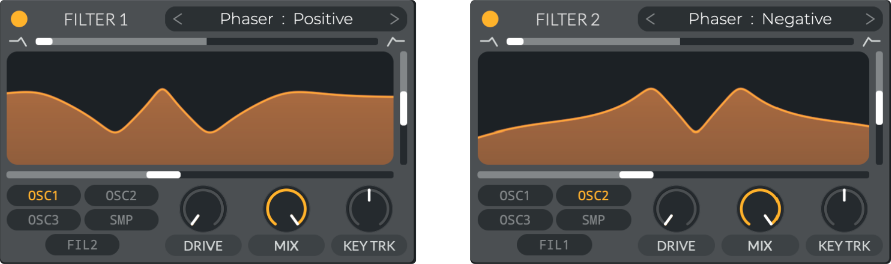
A phaser is a type of filter that creates moving notches or peaks in the frequency spectrum. This is achieved by using all-pass filters to adjust the signal's phase. Mixing this with the original signal creates phase cancellation, with constructive interference when in-phase and varied cancellation points when inverted.
The controls are the same as for the analog filters (blend, cutoff, resonance, drive, mix, and key tracking). The
blend
control morphs between fewer and more notches in the frequency spectrum.
The "Positive" and "Negative" options refer to whether the phaser output is inverted.
Positive
: The phase is not inverted, resulting in a conventional phasing effect with smooth notch modulation.
Negative
: The phase is inverted, resulting in a more pronounced and dynamic modulation character, emphasizing the sweeping notches and potentially creating a more extreme or contrasting tonal effect.
V35 | Low-pass filter
Filters.html | documentation and visible configuration; not a new native test
Analog, Dirty, Ladder, & Digital Filters
Retained observation
The filter-family menu includes Analog, Dirty, Ladder, Digital, Diode, Formant, Comb and Phaser. Analog subtypes include 12/24 dB, Notch Blend, Notch Spread and B/P/N. Blend, cutoff, resonance, drive, mix, keytrack and input routing are all separate controls. Choose the family and graph before optimizing scalar values.
Source SHA-256: 3bb92dcbc247c7dde143595cdf9f24f7650f2c794c036044a57c5f470e3a0efe Image SHA-256: 893bab379caec8b65389e5e72dd29bc44cfa7dfb5f86c5e1432b44824bfd1f08 Original URL: https://davidmvogel.com/img/vital-images/lowpass-filter.svg
V36 | Common filters
Filters.html | documentation and visible configuration; not a new native test
Analog, Dirty, Ladder, & Digital Filters
Retained observation
Six response plots show LP, HP, BP, notch, double-notch and peak behavior from different blend/subtype settings. A filter is not merely a high-frequency loss. Moving a notch or peak across partials can change identity while leaving much of the spectrum present; retain shape as well as cutoff motion.
Source SHA-256: 3bb92dcbc247c7dde143595cdf9f24f7650f2c794c036044a57c5f470e3a0efe Image SHA-256: 589d9f0008e059ef6fe07ca870cadef2542875f7e384178101234e2acd74631a Original URL: https://davidmvogel.com/img/vital-images/common-filters.svg
V37 | Diode filter
Filters.html | documentation and visible configuration; not a new native test
Diode filter
Retained observation
The Diode comparison at Blend 1.75 shows Low Shelf retaining low content while Low Cut removes it steeply during LP-to-BP transition. This distinction offers control over low-body retention during spectral motion. These are illustrative responses, not evidence that either fixes a particular reference.
Source SHA-256: 3bb92dcbc247c7dde143595cdf9f24f7650f2c794c036044a57c5f470e3a0efe Image SHA-256: abcb150573095e2581479b6b52082141948ebfd4bcb4561f3f415ad3129511f7 Original URL: https://davidmvogel.com/img/vital-images/diode-filter.svg
V38 | Formant filter
Filters.html | documentation and visible configuration; not a new native test
Formant filter
Retained observation
Formant AOIE replaces ordinary controls with X, Y, formant transpose, Peak and Spread. Multiple resonances move as a coordinated structure. Use X/Y trajectories for vowel-like evolution when appropriate; an amplitude envelope alone cannot specify that structure, and not every vowel impression proves a formant filter.
Source SHA-256: 3bb92dcbc247c7dde143595cdf9f24f7650f2c794c036044a57c5f470e3a0efe Image SHA-256: 19171b0fba70f465d70e7448de6b8d726fc9c89ce91b75b63f5546ea9e53b895 Original URL: https://davidmvogel.com/img/vital-images/formant-filter.svg
V39 | Comb filter
Filters.html | documentation and visible configuration; not a new native test
Comb filter
Retained observation
The comb graphic distinguishes the main cutoff/pitch control from an additional Cut control, with resonance and keytracking. This separates spacing/tuning of the repeated resonances from spectral attenuation around them. Modulating one is not equivalent to modulating the other.
Source SHA-256: 3bb92dcbc247c7dde143595cdf9f24f7650f2c794c036044a57c5f470e3a0efe Image SHA-256: 77d464f4cee4ef475fbb845aba7ee8a81bd539c7c4b5dca8b6d122b4a9608b5d Original URL: https://davidmvogel.com/img/vital-images/comb-filter.svg
V40 | Phaser filter
Filters.html | documentation and visible configuration; not a new native test
Phaser filter
Retained observation
Positive and Negative phaser-filter responses show different peak/notch patterns. The example also routes OSC1 and OSC2 to separate filters. Response polarity, branch routing and motion are available independently; neither polarity is a universal improvement or a replacement for checking the combined output.
Source SHA-256: 3bb92dcbc247c7dde143595cdf9f24f7650f2c794c036044a57c5f470e3a0efe Image SHA-256: 49340dc29641234518a2e30532cd3f4d16f65338d9e434d96fc4f848d5fc6a8c Original URL: https://davidmvogel.com/img/vital-images/phaser-filter.svg